GRUPPI DI CIRCOLAZIONE PER BIOMASSA / BIOMASS HEATING GROUPS
Mod. 25000 - NOVAMAT
da
35
kW
a
100
kW
Art. 25000 NOVAMAT T
TERMOSTATICO
THERMOSTATIC
DATI TECNICI
Diametro nominale
Pressione max.
Temperatura di lavoro max.
Temperatura di lavoro min.
Valvole di intercettazione (opzionale)
Termometri (se presenti)
DN25
TECHNICAL DATA
Nominal Diamete
Max. pressure
Max operating temperature
Min. operating temperature
Installation valves (optional)
Thermometers (if any)
Pressure check valve opening
Fluid
External dimensions
IP protection grade
Heat generator connections
Interaxes
Heating system connections
Interaxes
DN25
8
7
6
5
3
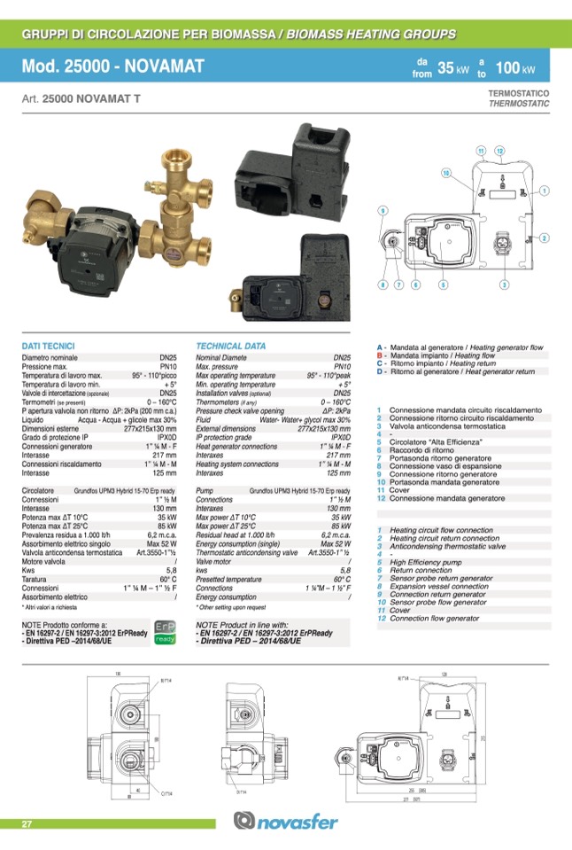
A - Mandata al generatore / Heating generator flow
B - Mandata impianto / Heating flow
C - Ritorno impianto / Heating return
D - Ritorno al generatore / Heat generator return
PN10
95° - 110°picco
+ 5°
DN25
0 – 160°C
ΔP: 2kPa (200 mm c.a.)
Liquido
Acqua - Acqua + glicole max 30%
PN10
95° - 110°peak
+ 5°
DN25
0 – 160°C
ΔP: 2kPa
Water- Water+ glycol max 30%
277x215x130 mm
IPX0D
1’’ 1⁄4 M - F
217 mm
1’’ 1⁄4 M - M
125 mm
1 Connessione mandata circuito riscaldamento
2 Connessione ritorno circuito riscaldamento
3 Valvola anticondensa termostatica
4-
P apertura valvola non ritorno
Dimensioni esterne
Grado di protezione IP
Connessioni generatore
Interasse
Connessioni riscaldamento
Interasse
277x215x130 mm
IPX0D
1’’ 1⁄4 M - F
217 mm
1’’ 1⁄4 M - M
125 mm
5 Circolatore “Alta Efficienza”
6 Raccordo di ritorno
7 Portasonda ritorno generatore
8 Connessione vaso di espansione
9 Connessione ritorno generatore
10 Portasonda mandata generatore
11 Cover
12 Connessione mandata generatore
Circolatore
Connessioni
Interasse
Potenza max ΔT 10°C
Potenza max ΔT 25°C
Prevalenza residua a 1.000 lt/h
Assorbimento elettrico singolo
Valvola anticondensa termostatica
Motore valvola
Pump
Connections
Interaxes
Max power ΔT 10°C
Max power ΔT 25°C
Residual head at 1.000 lt/h
Energy consumption (single)
Thermostatic anticondensing valve
Valve motor
Taratura
Connessioni
Assorbimento elettrico
* Altri valori a richiesta
NOTE Prodotto conforme a:
60° C
1’’ 1⁄4 M – 1’’ 1⁄2 F
/
Presetted temperature
Connections
Energy consumption
* Other setting upon request
NOTE Product in line with:
60° C
1 1⁄4”M – 1 1⁄2” F
/
Grundfos UPM3 Hybrid 15-70 Erp ready
1’’ 1⁄2 M
Grundfos UPM3 Hybrid 15-70 Erp ready
130 mm
35 kW
85 kW
6,2 m.c.a.
Max 52 W
Art.3550-1’’1⁄2
/
Kws
5,8
1’’ 1⁄2 M
130 mm
35 kW
85 kW
6,2 m.c.a.
Max 52 W
Art.3550-1’’ 1⁄2
/
1 Heating circuit flow connection
2 Heating circuit return connection
3 Anticondensing thermostatic valve
4-
5 High Efficiency pump
6 Return connection
7 Sensor probe return generator
8 Expansion vessel connection
9 Connection return generator
10 Sensor probe flow generator
11 Cover
12 Connection flow generator
- EN 16297-2 / EN 16297-3:2012 ErPReady
- Direttiva PED –2014/68/UE
- EN 16297-2 / EN 16297-3:2012 ErPReady
- Direttiva PED – 2014/68/UE
27
130
A) 1"1/4
255
277 (327)
120
80
40
C) 1"1/4
D) 1"1/4
(305)
B) 1"1/4
kws
5,8
9
1
2
from
da
17
ktWo
11
a
47
kW
from
to
10
12
1
0
0
2
1
5

