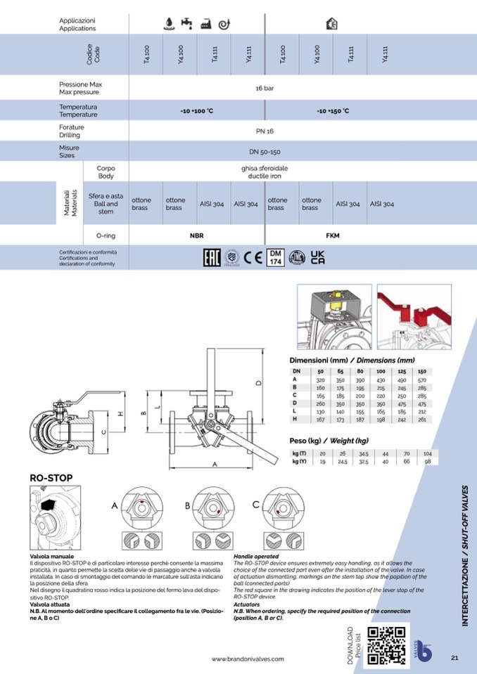
RO-STOP
Valvola manuale
A
B
C
Applicazioni
Applications
Pressione Max
Max pressure
Temperatura
Temperature
-10 +100 °C
16 bar
PN 16
DN 50-150
ghisa sferoidale
ductile iron
-10 +150 °C
Forature
Drilling
Misure
Sizes
Certificazioni e conformità
Certifications and
declaration of conformity
Corpo
Body
Sfera e asta
Ball and
stem
O-ring
ottone
brass
ottone
brass
AISI 304
AISI 304
ottone
brass
ottone
brass
AISI 304
FKM
AISI 304
Il dispositivo RO-STOP è di particolare interesse perchè consente la massima
praticità, in quanto permette la scelta delle vie di passaggio anche a valvola
installata. In caso di smontaggio del comando le marcature sull'asta indicano
la posizione della sfera.
Nel disegno il quadratino rosso indica la posizione del fermo leva del dispo-
sitivo RO-STOP.
Valvola attuata
N.B. Al momento dell'ordine specificare il collegamento fra le vie. (Posizio-
neA,BoC)
The RO-STOP device ensures extremely easy handling, as it allows the
choice of the connected port even after the installation of the valve. In case
of actuation dismantling, markings on the stem top show the popition of the
ball (connected ports)
The red square in the drawing indicates the position of the lever stop of the
RO-STOP device.
Actuators
N.B. When ordering, specify the required position of the connection
(position A, B or C).
NBR
A
32,5
40
66
98
Handle operated
www.brandonivalves.com
21
Dimensioni (mm) / Dimensions (mm)
DN
50
65
80
100
125
150
A
320
350
390
B
160
175
195
C
165
185
200
D
260
350
350
L
130
140
155
H
167
173
187
Peso (kg) / Weight (kg)
430
490
570
215
245
285
220
250
285
350
475
475
165
185
212
198
242
261
kg (T)
kg (Y)
20
26
19
24,5
34,5
44
70
104
D
O
W
N
L
O
A
D
P
r
i
c
e
l
i
s
t
T
4
.
1
1
1
V
A
L
V
E
S
I
N
T
E
R
C
E
T
T
A
Z
I
O
N
E
/
S
H
U
T
-
O
F
F
V
A
L
V
E
S
c
H
C
o
d
i
c
e
C
o
d
e
B
T
4
.
1
0
0
L
D
M
a
t
e
r
i
a
l
i
M
a
t
e
r
i
a
l
s
Y
4
.
1
0
0
T
4
.
1
1
1
Y
4
.
1
1
1
T
4
.
1
0
0
Y
4
.
1
0
0
Y
4
.
1
1
1

