Preliminary indications
WE strongly advise against connecting 2 or more WW-10 panels
in series, in order to avoid pressure losses that are too high, and
problems with bleeding out the air.
If the panel is put in a position in which it is not possible to
connect the WW-10 panel to the supply line directly, use an
DN10 sleeve and a piece of DN10 pipe to form the extension.
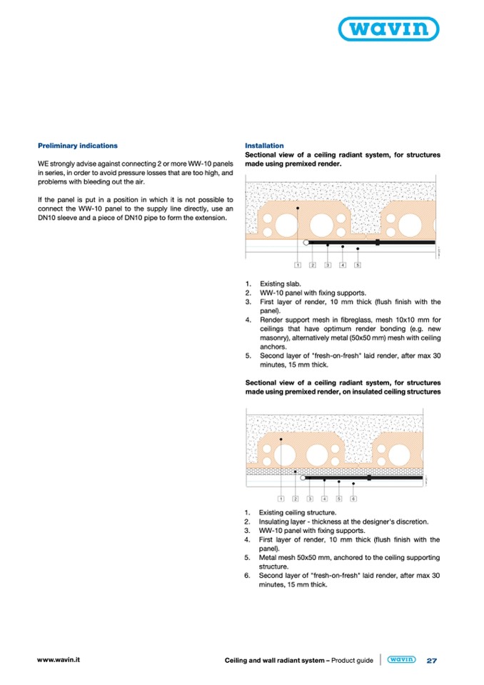
Installation
Sectional view of a ceiling radiant system, for structures
made using premixed render.
www.wavin.it
Ceiling and wall radiant system – Product guide
27
1. Existing slab.
2. WW-10 panel with fixing supports.
3. First layer of render, 10 mm thick (flush finish with the
panel).
4. Render support mesh in fibreglass, mesh 10x10 mm for
ceilings that have optimum render bonding (e.g. new
masonry), alternatively metal (50x50 mm) mesh with ceiling
anchors.
5. Second layer of "fresh-on-fresh" laid render, after max 30
minutes, 15 mm thick.
Sectional view of a ceiling radiant system, for structures
made using premixed render, on insulated ceiling structures
1. Existing ceiling structure.
2. Insulating layer - thickness at the designer's discretion.
3. WW-10 panel with fixing supports.
4. First layer of render, 10 mm thick (flush finish with the
panel).
5. Metal mesh 50x50 mm, anchored to the ceiling supporting
structure.
6. Second layer of "fresh-on-fresh" laid render, after max 30
minutes, 15 mm thick.

